3D printing is changing the way we make things, especially when it comes to creating physical products. This is a learning path that will cover the history of 3D printing, as well as how business and consumers can use additive manufacturing to their advantage.
Many different manufacturing technologies are used by engineers to produce different parts and products. Traditional technologies like CNC, injection molding and casting are very common and often used in production of parts.
These manufacturing techniques are classified into three categories as below.
Formative manufacturing:
In this type of process raw material is shaped into required product by using heat or pressure. Processes like injection molding, die casting, stamping and forging are used to form products. Large range of materials used in this process for both plastic and metal.
These manufacturing processes are meant for high volume production and cost of the product is lower. High initial investment is needed in tools like dies and molds.
Subtractive manufacturing:
Solid blocks of different material are cut by different processes to get the final shape of product. CNC machining, lathe machining, drilling, cutting and turning are the common processes of manufacturing.
These are cost effective methods of production and many different materials can be processed. A lot of designing and drafting is required for products. Cam and CAD drawings are needed to feed into machines to run the process.
In this type of manufacturing, process tools used for different operations cannot reach all the surfaces or axis of product during machining. This is the biggest limitation of the process.
Due to this, complex parts are difficult and time consuming to produce. It also increases the manufacturing cost and time.
Latest machines like 5 axis CNC has reduced these limitations to some extent.
Apart from this, a large amount of materials are removed in the process which is considered as waste.

Additive manufacturing:
It is commonly known as 3D printing.
Any geometrical part can be produced using 3 D printer.
There is no need of expensive tooling and very low initial investment.
Mostly used for rapid prototyping and low volume production.
3D printing has mainly two problems.
- parts produced are not fully dense
- Limitation of repeatability. Variations can occur due to differences in cooling and curing
3D Printing
There are many different technologies and processes to manufacture parts.
5 basic steps used in each process form design to final product.
1) 3D design or drawing
Digital models are produced using CAD software or by 3D scanning. While designing 3D printed models, different parameters of geometry, shape, process limitations and process materials are considered.
2) STL files
CAD designs or files are then converted to STL files. These files 3D printers can read and print a part. This file is called Stereolithography (STL) or standard triangle language file.
Most of the CAD software can produce STL files
After Generating STL file, the design is converted into layers that will be used to print the product. This process is done by software called slicer.
This Slicer software converts the STL file into G code. G code is a program which can control and command automated machines like 3dprinter 2D printer and CNC machines.
This slicer program is very important as it allows operator to choose printing parameters like layer height, resolution and support locations.
Click Here: The List of Free 3D printing Slicer software
3) Printing
Different printing technique used different raw material and process to print parts.
4) Removing print from machine:
Printed part is then removed from machine or the build platform. This process is very easy in small scale printers. In case of industrial 3D printer and some technologies, we must follow the specific procedures to remove the prints. It is highly technical and skilled process.
5) Post processing:
Printed parts are then carried away for further processing. In some techniques it is required to cure the part under UV light and in others the parts are used right away.
Many printers use supports to print the parts and those are also removed in this stage very carefully.
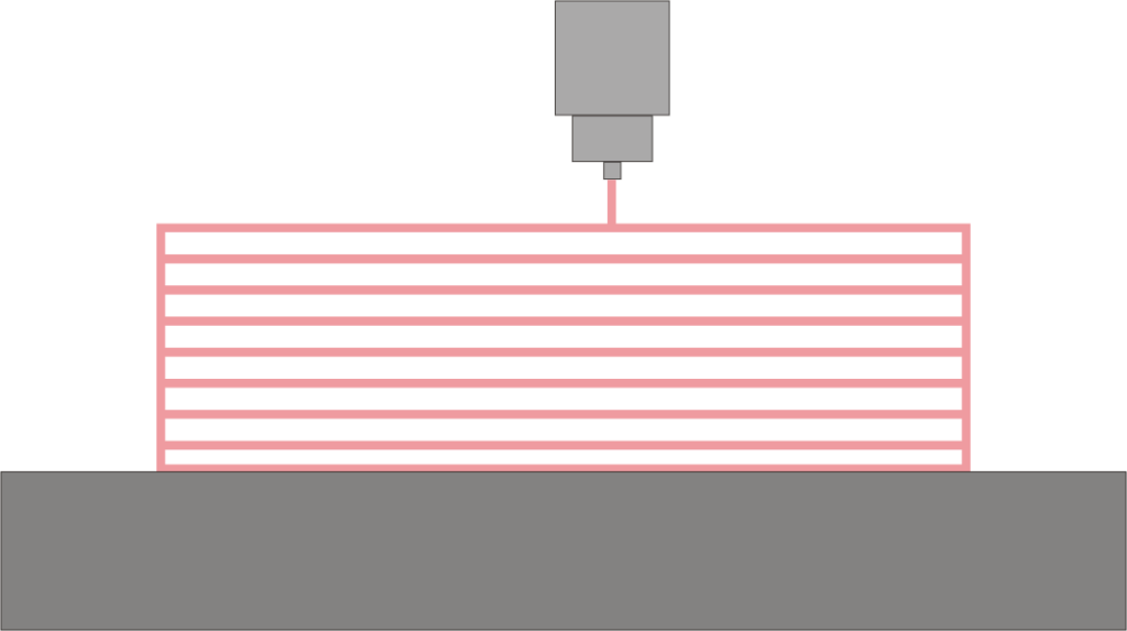
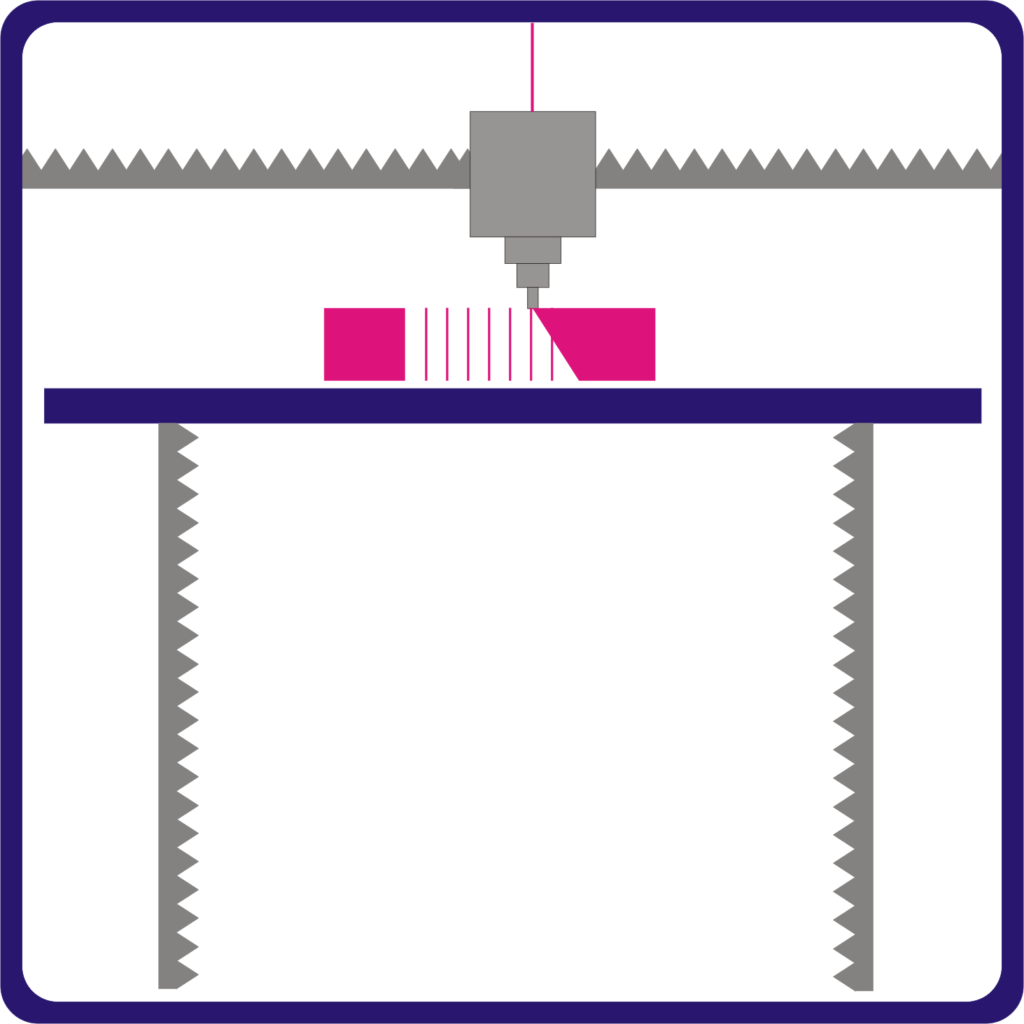
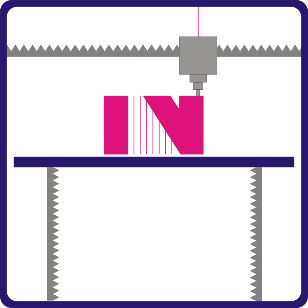
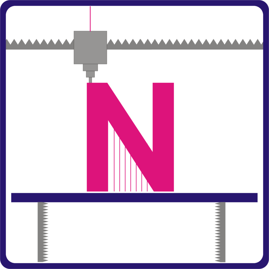
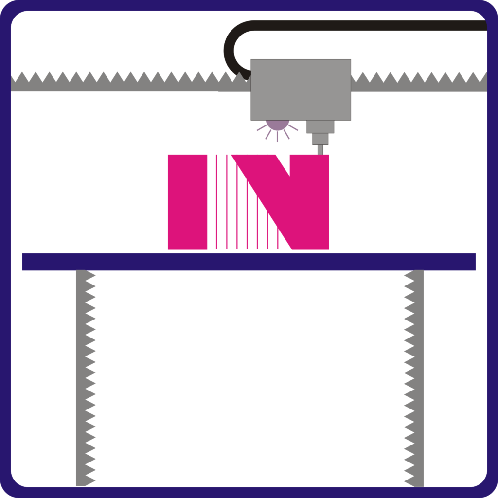
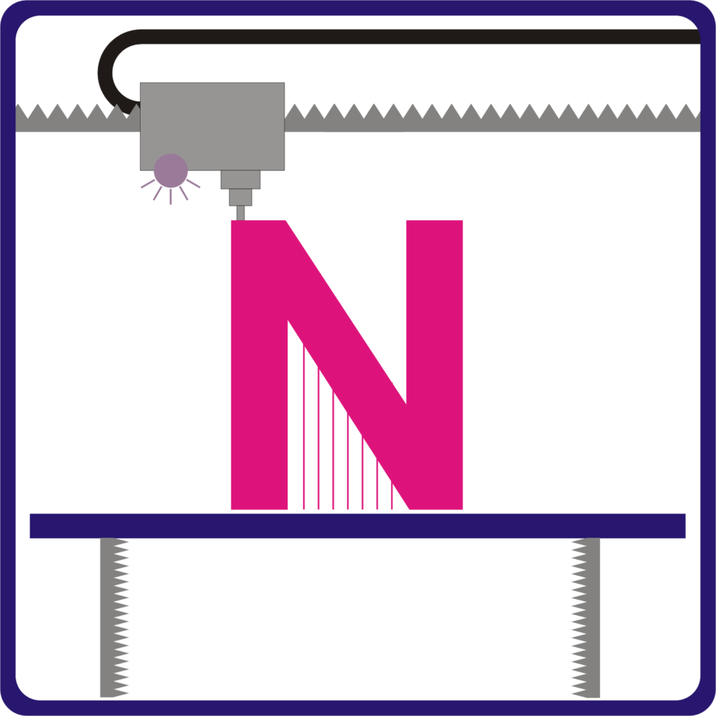
FFF (Fused Filament fabrication) 3D printer Technology
In this type of printing, polymer material in the form of filament is melted and printed. Using a printing head which melts the material and it is thrown on to the exact location of printing and solidified into and object or part. There are different types of 3D printer filaments available for printing.
Printing is carried out layer by layer. Once a layer is finished, printer head moves to the location to start next layer. This technology is commonly known as FDM (Fused Deposition modeling)
Build Volume:
It is the area a printer can print on.
Desktop FDM printer generally can print on 200 X 200 X 200 mm build chamber and industrial printer can go up to 1000 X 1000 X 1000mm build volume.
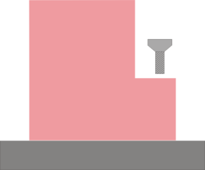
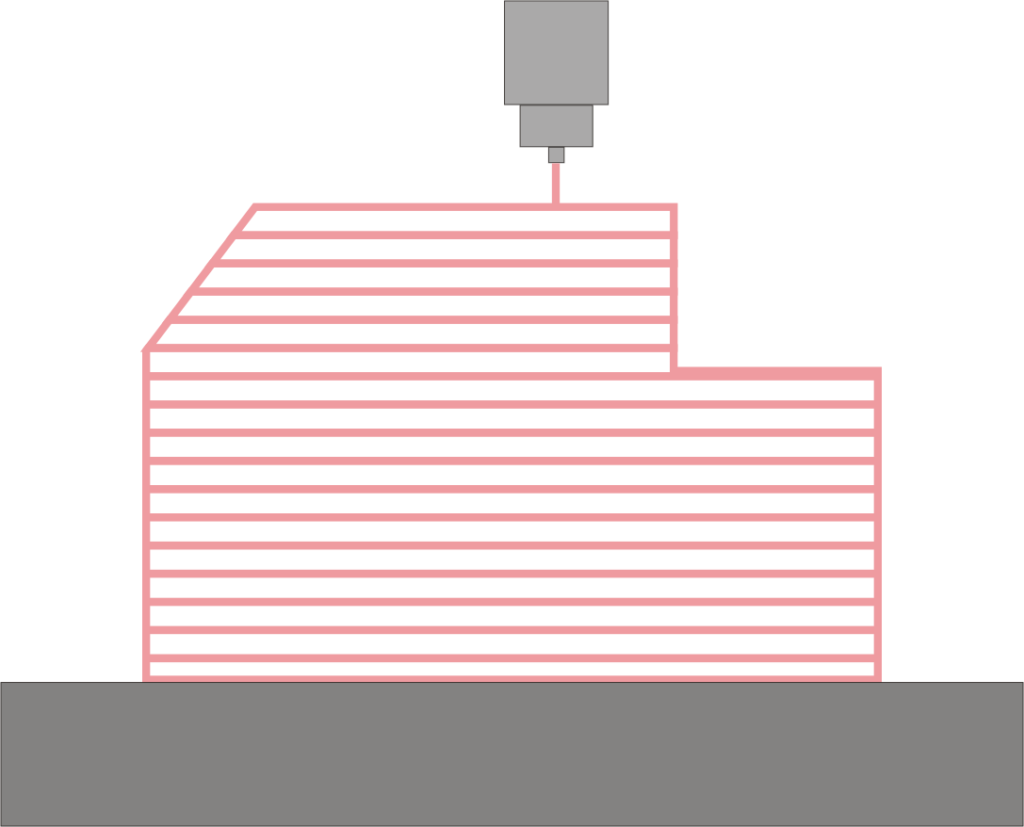
Support structure:
These supports basically allow printer to print those areas which are hanging and cannot hold the material.
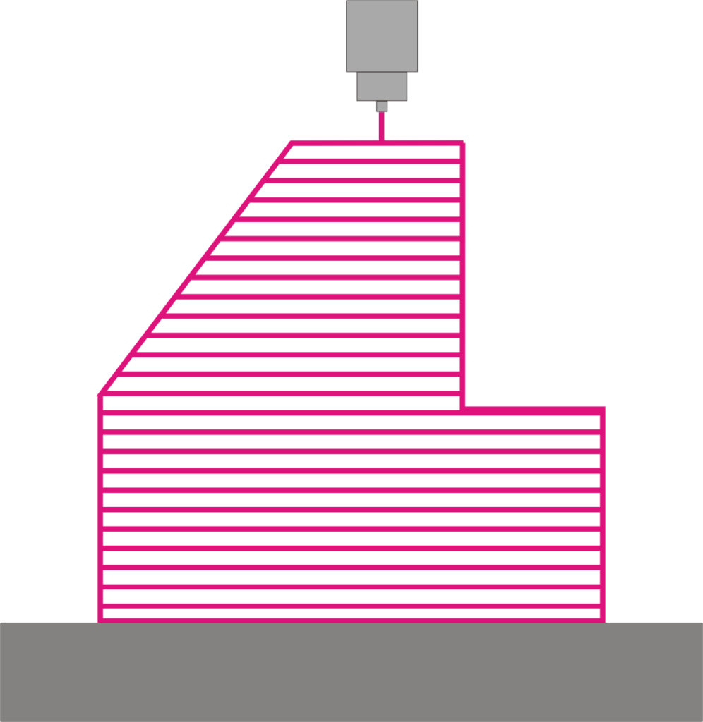
Generally overhangs less than 45 degrees angle needs supports and overhangs more than 45 degrees do not need support.
These supports are removed in post processing by cutting or any other method. There is new type of Polymer material called Poly vinyl alcohol (PVA) which is soluble in water. This type of support is easier to remove. As this is new development it is also costly.
Infill:
Inside structure of the printed part is called infill. Generally FFF parts are not fully dense or solid from inside. In order to save build time and material parts are printed with variable infill percentages.
Wrapping:
If a part needs high strength, it can be printed with 80% solid. Some parts which are only used for fitting and prototypes can be printed with 10% or 20 % solid material.
It is a common problem in FDM 3D printing. This printing is done layer by layer and because of different temperatures of cooling and heating, layers is pulled together. This leads to wrapping and distortion in the parts.
Shrinking and wrapping behavior of materials is hard to predict and thermoplastics with high printing temperature are more at risk.
Dimensional Accuracy is +/- 0.5 % and Z direction is more accurate.
Pros and cons:
FFF machines and materials are low cost. Most popular 3d printer for all people and non commercial use. These can be used for prototyping, educational purpose and hobbies and DIY projects.
Parts printed are weaker due to different infill percentages. Stronger parts produced will have more material cost and build time.
The layer by layer printing method gives visible layer lines on the edges of the parts.
Applications:
Jigs and fixtures
Investment casting patterns
Electronic housing
Form and fit testing or prototyping
Educational purposes
DIY projects and hobbies
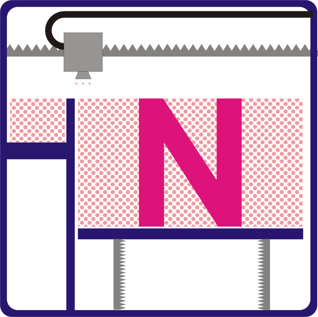
VAT Polymerization:
VAT polymerization is a process of 3d Printing uses a photo polymer which is cured by light to form a part.
There are two types of VAT polymerizations processes.
Stereolithography (SLA) and Direct Light processing (DLP)
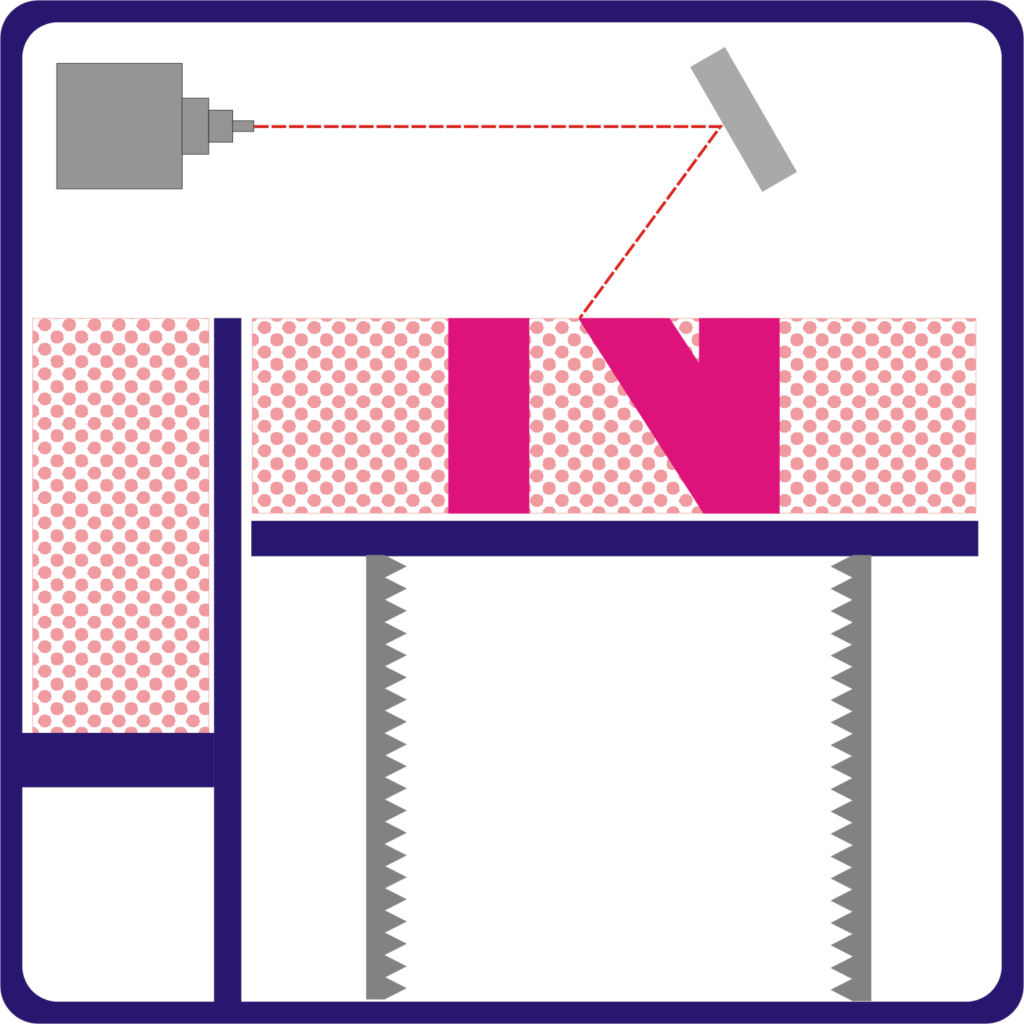
Stereo lithography (SLA): This process used laser beam to cure the layers of a part. This beam is directed using mirrors on X axis and Y axis across the print area. SLA machines use Solid State Lasers to cure the parts.
Direct Light processing (DLP): Direct Light processing is similar to SLA process. The only difference is, it prints a complete layer by projecting image of complete layer. Image of each layer consist of small pixels which forms small cubes on the print.
DLP printer is faster than SLA 3D printer.
SLA printer uses point later to cure a spot on the single layer of a part. In DLP 3D printer, it uses light projector with cross section of the layer image to expose the complete layer at once.
Laser beam spot size or light projector resolutions govern the surface finish and accuracy of the part.
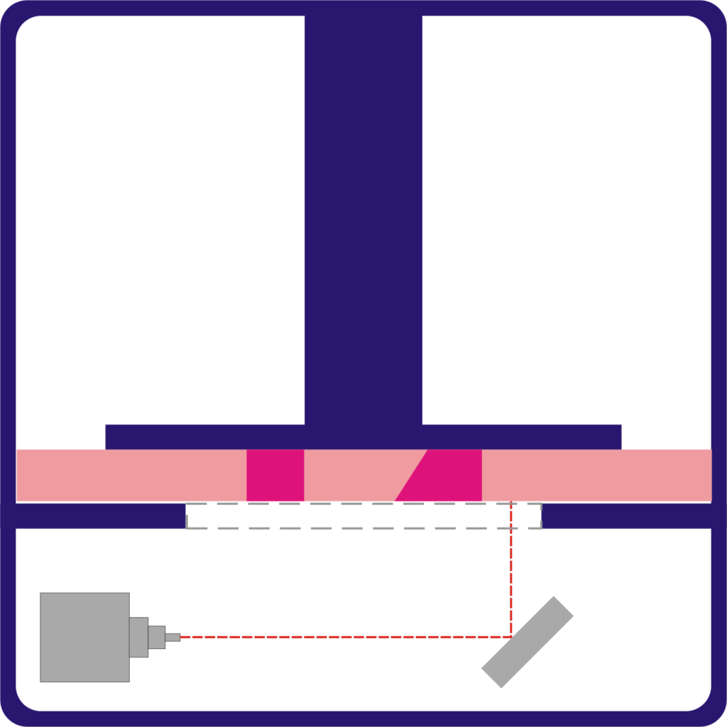
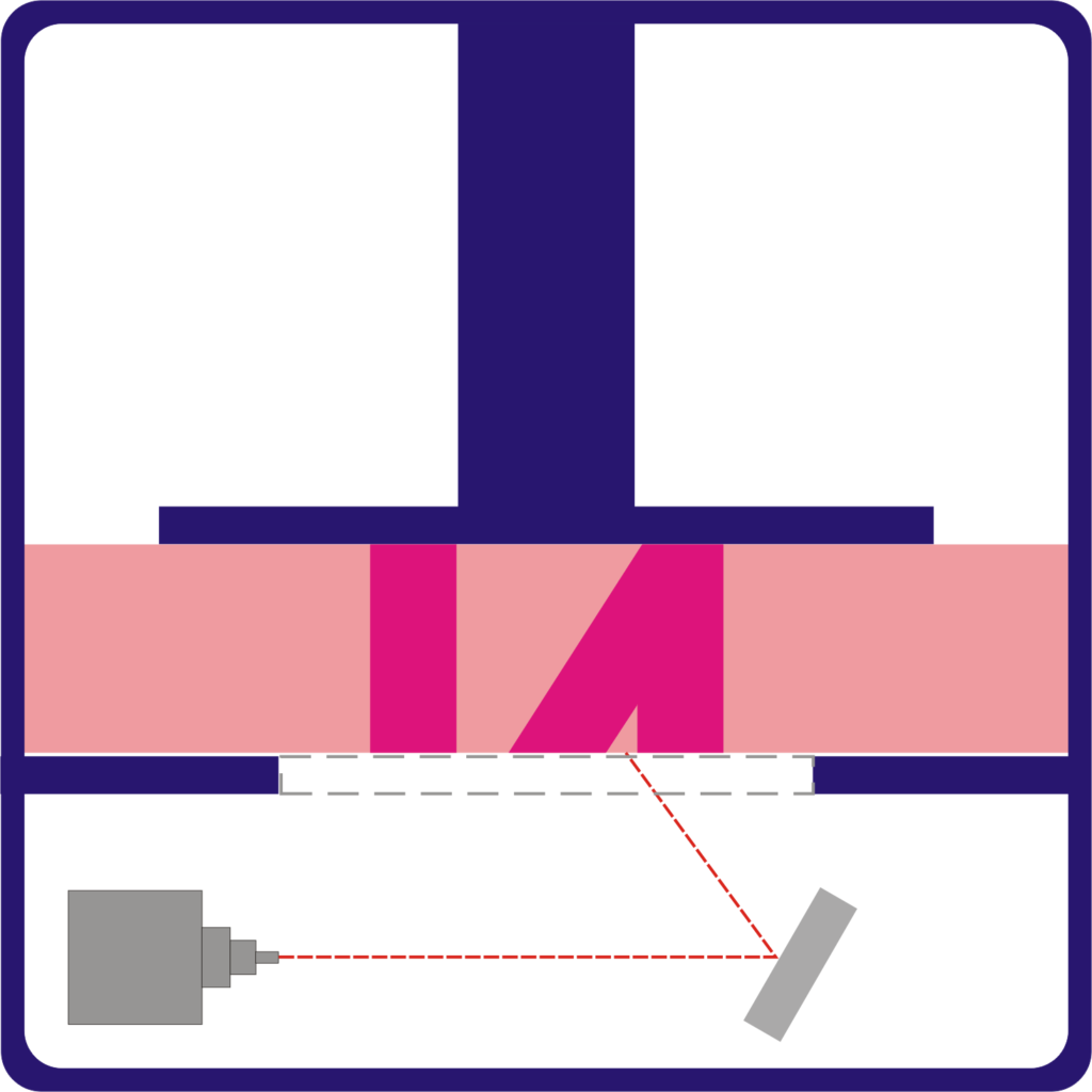
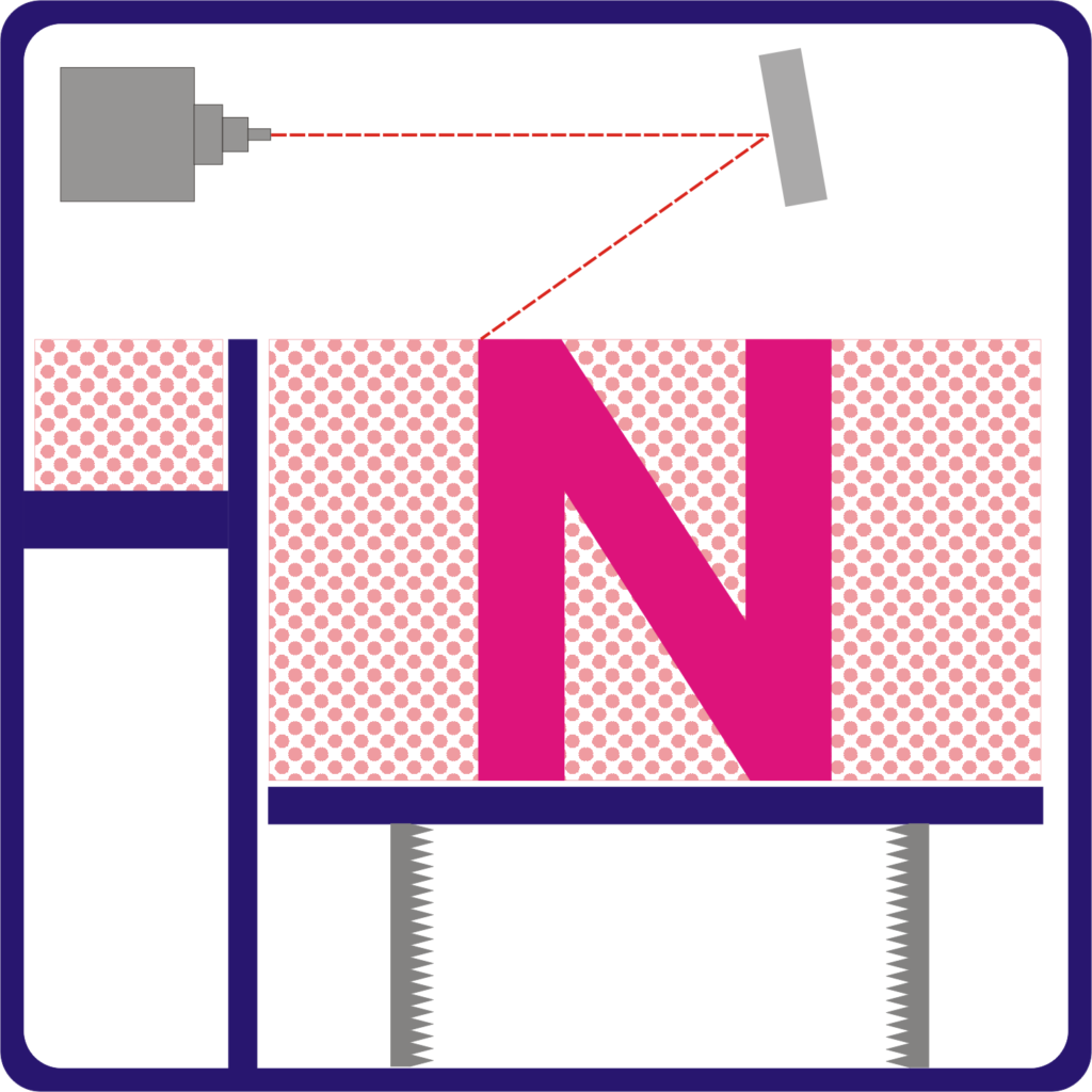
Bottom Up and Top down Orientation:
SLA and DLP resin 3D printer print parts in two ways. One is bottom up and Top down orientation.
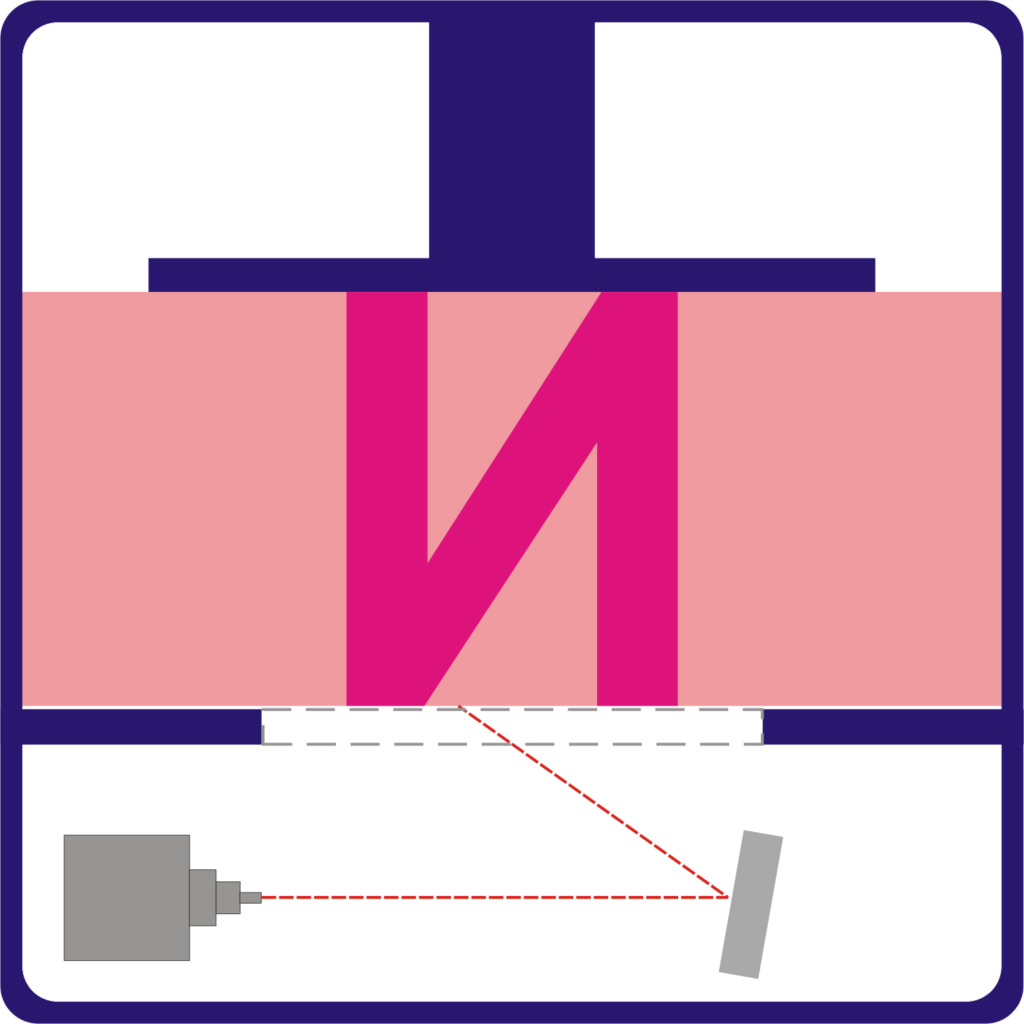
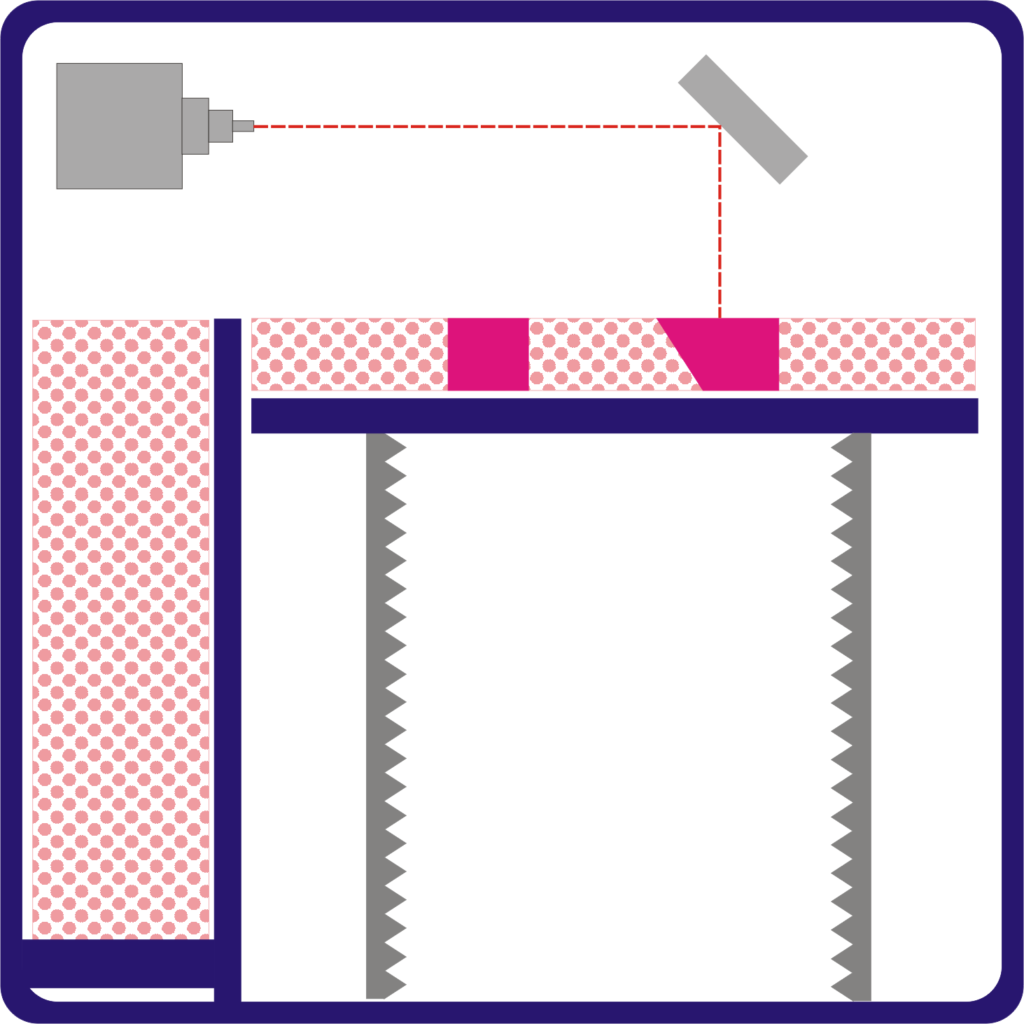
In Bottom up type, light source is positioned below the resin VAT or machine with the transparent bottom. Top layer of the part is printed first and building platform moves up.
In Top down orientation, light source is positioned on the top of the VAT and building platform moves down.
Very less resin is required in bottom up process and the size of machine is smaller. It is also easier to control the thickness of the each layer.
Transparent bottom needs to be cleaned, maintained and replaced frequently to achieve good quality prints.
Print can fall in the process due to its own weight leading to print failure.
Parts must be printed at an angle which increases build time and cost.
Top down process is the faster process as we don’t need to separate the build plate form after printing each layer.
The forces on the part are much lower and it is a reliable process.
Parts are not printed at an angle which requires less support material.
SLA or DLP process can produce parts with +/-0.5 to +/-0.15 mm accuracy. These processes also need supports to produce accurate parts. Shrinkage and wrapping are common problems in case of large flat surfaces and long unsupported spans.
Pros and cons:
VAT polymerization can produce parts with excellent surface finish and high degree of accuracy.
Photopolymers are brittle and not strong enough to produce functional parts.
Photopolymer parts have limited life as it degrades in the presence of sunlight.
Common applications:
Jewellery (investment casting)
Injection mold like prototypes
Dental Application
Hearing Aids
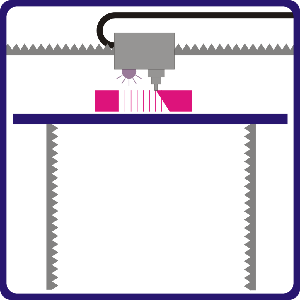
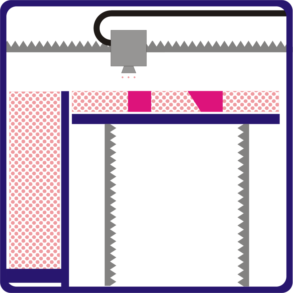
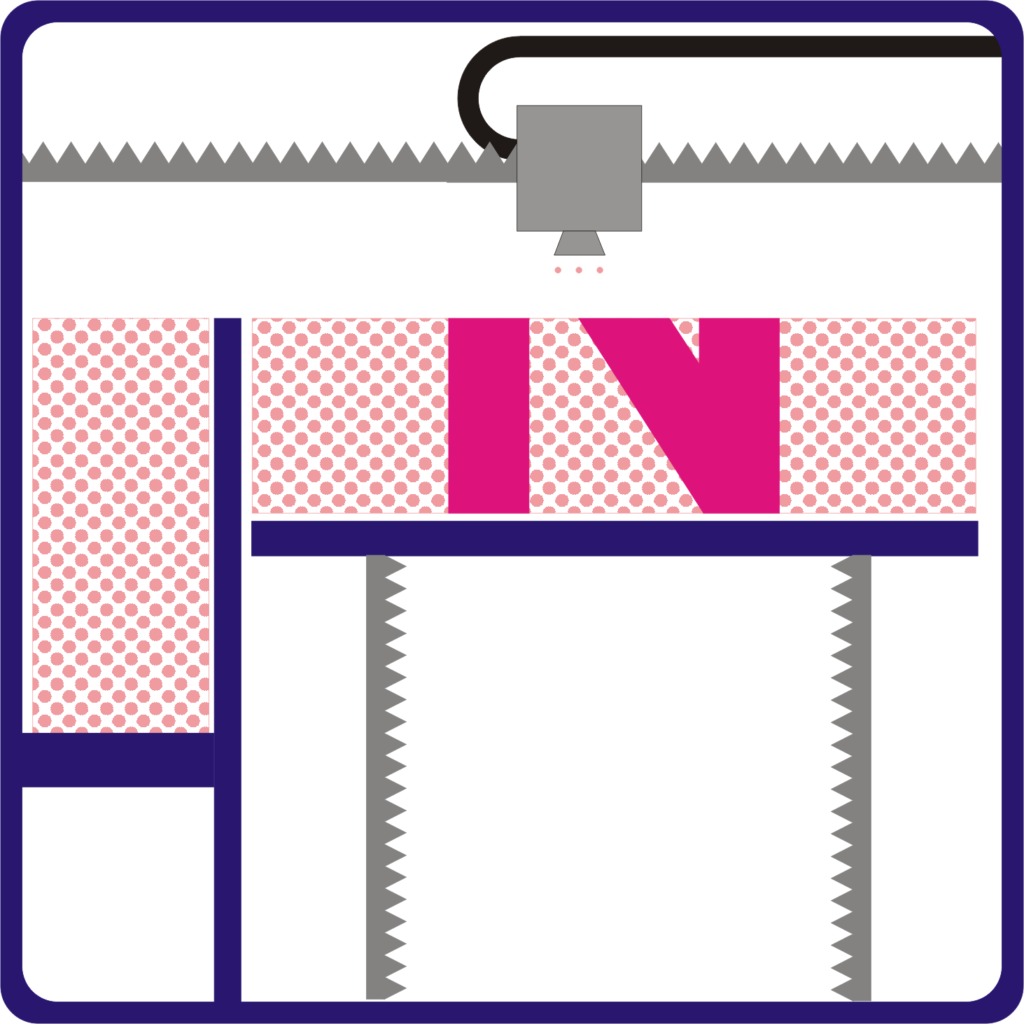
Powder Bed Fusion (Polymer):
This technology uses polymer powder to produce parts and generally known as Selective Laser Sintering (SLS)
In this process, polymer powder is heated up to just below melting temperature and spread over build platform by coating mechanism. A laser beam scans the cross section area and selectively fuses the material to become solid. In this process mirrors are used to focus the laser.
Building platform is moved down one layer thickness in height and the same process carried out for next layer. This is how the complete part is build layer by layer.
SLS process do not need supports to the parts as the powder itself act as supporting material and removed easily from the bin after finishing.


Powder bin:
In order to use build volume effectively, it is very important to pack parts with optimal orientation and location in the bin. This can be done by the printer software. This process can also be done manually by operator in the printer software.
The average build volumes for these printers are 300 X 300 X 300mm and bigger machines with build volume up to 750 X 550 X 550mm.
Laser sintering process causes particles to fuse together in multiple directions. This results in parts that are homogeneous and strongly bonded.
SLS process gives dimensional accuracy up to +/- 0.3mm
Shrinkage and wrapping is very less and most 3D laser printer (SLS printer) can account for this in build phase.
Pros and Cons:
In SLS process functional parts with complex geometry can be produced
Parts do not require any support material which results in no post processing and parts produces are with consistent surface finish.
Process material and SLS 3D printer cost is higher.
Lead time for production is higher due to time consuming heating and cooling stages of material.
Applications:
Complex hollow parts can be produced as this process is not dependent on support material.
Parts which requires strength and complex geometry.
Low run part production.
Material Jetting Technology:
This technology is similar to an inkjet printer however, instead of printing a single layer of ink, may layers are build on one another to form the part.
There are two heads one with printing photopolymer and another with UV curing light. Photopolymer sprayed on each layer is cured by UV light. This process is repeated and part is built.
Most of the 3 d printing processes material layers are deposited in point wise or spot wise. In Material jetting it is done in line wise fashion. It increases the process speed.
This is the only technology which allows printing multi material together and full color parts.
Drop On Demand 3D Printing(DOD):
These printers have two printing heads one to deposit printing material and another for dissolvable support material. DOD printers follow a set path and deposit material to make cross section area of a layer.
DOD printers mainly used for producing wax like patterns mainly used in investment casting and mould making.
This printing process also requires support materials like FFF or other machines.
Material Jetting is one of the accurate 3D printing processes which can print layer as low as 16 microns. This can give smooth surfaces and high degree of accuracy.
Material Jetting offers two kinds of surface finishes glossy and matte. Matte surface is produced by adding thin layer of support material on entire part regardless of the requirement of support.
Benefits and limitations:
Material Jetting is the most dimensionally accurate 3D printing process.
Parts produced b y this method have smooth surfaces like injection molded parts.
Material jetting can produce homogenous parts as the layers are fully cured together.
In this method, Parts produced have very low strength. The materials used in this process produce parts with poor mechanical properties.
This process is very costly because of the raw material cost.
Applications:
Medical Models for educational purposes
Injection mould like prototypes
Low run injection moulds
Full color visual prototypes
Binder Jetting:
In Binder Jetting, A binding agent is deposited on the powder bed to form a part layer by layer. These layers bind together to form a part,
Just like laser sintering (SLS), powder layer is coated on the build platform. In sintering a laser is used to cure the layer of part. In Binder Jetting method, binder is deposited in the form of droplets to form the part layer.
Once the layer has been formed, build platform is lowered and the process is repeated until the complete part is produced.
Binder jetting has two categories: sand printing and metal 3D printing
Sand binder jetting is the low cost method to produce parts from sand. Mainly sandstone and gypsum are used in this process.
Full color models can be produced using sand binder jetting. One head deposits binder and another head deposits required color on the model.
Metal Binder Jetting is also used to produce metal parts. A polymer binding agent is deposited on the metal powder to form layer and parts. The polymer binder used in the process is removed or burnt by heating the part. This leaves the part with low density.
In order to produce metal functional parts with high density, two different methods are used to improve the density.
Bronze infiltration: Once the parts formed by using polymer binder, they are places in heating furnace to remove the binder. After this process part is with low density and pores or voids. These pores or voids are filled with bronze powder and parts are again sintered in the furnace. This will result in 90% dense parts.
Furnace sintering: Metal parts produced in this process are cured in oven to remove the polymer binder. Parts are then sintered in a furnace to achieve high density. The main limitation of this process is shrinkage which should be accommodated in the design stage.
Dimensional accuracy of the parts will be +/- 0.2mm and these methods do not need support materials for parts.
Pros and Cons:
This process does not use any heat to produce the part. This will reduce the operating cost and parts will not suffer from heating and cooling stress.
Binding materials used are low cost and binder jetting can produce large parts for molding application.
The main limitation of the process is the need of secondary process to achieve higher density or mechanical properties.
Common applications:
Production of Full color parts
Sand casting
Production of functional metal parts
Powder Bed Fusion 3D Printing(Metals):
In Metal powder bed fusion technology, metal powder is fused together layer by layer to make complete part. Depending on the power source there are different methods are used in this technology. Those are as below.
DMLS and SLM are the two types known as Direct Metal Laser Sintering and Selective Laser Melting. Both the methods are quiet similar to SLS 3D printing which we seen in earlier in this article.
In DMLS, metal powder is not completely melted. It is heated up to a temperature which fuses the particles together. On the other hand, SLM uses the laser to melt the powder completely and forms homogenous part.
Due to this difference in melting, DMLS process is used to form alloy parts and SLM is used to form single metal part.
Powder used into the process provides physical support but still both the methods need supports to limit the distortion or wrapping of the parts.

EBM is another process in powder bed fusion known as Electron Beam Melting.
This method uses a higher energy source of electrons to melt the powder. A focused electron beam melts the material in the layer and this is how the part is formed.
This method produces parts with high density and accuracy. EBM process only used with conductive metals and is carried out in the vacuum.
In this method, parts are produced with dimensional tolerance of +/- 0.1mm. Parts are subject to shrinkage and wrapping. This is reduced by providing extra support in the process.
Pros and Cons:
DMLS and SLM techniques produce complex parts with high degree of accuracy and strength.
The main limitation is the machine and material cost. The build volume of the largest printer in this category is smaller compared to other 3D printing methods.
Common applications:
Used to produce low volume and highly complex geometries
Dental applications
Medical applications
Aerospace and automotive applications